HiSport
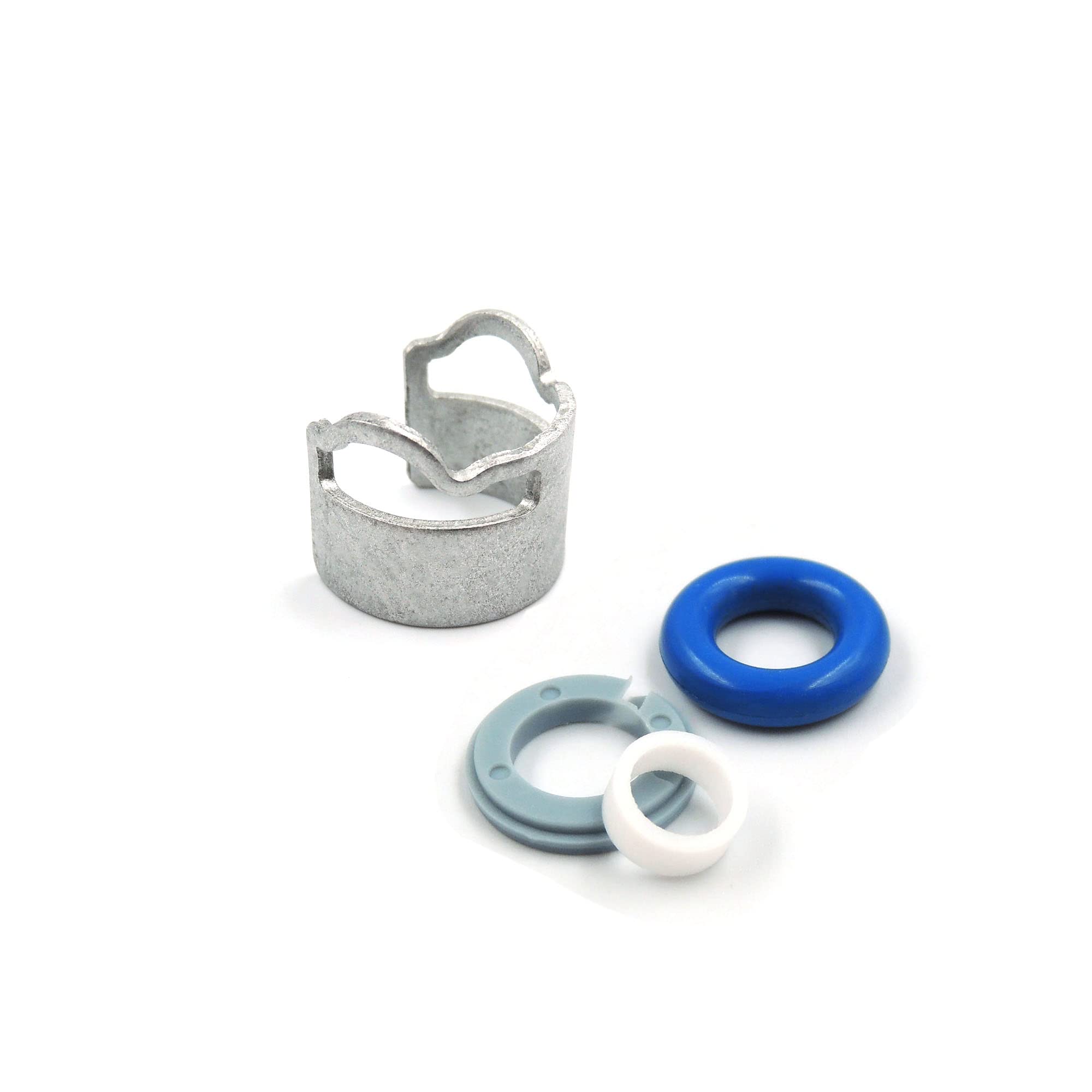
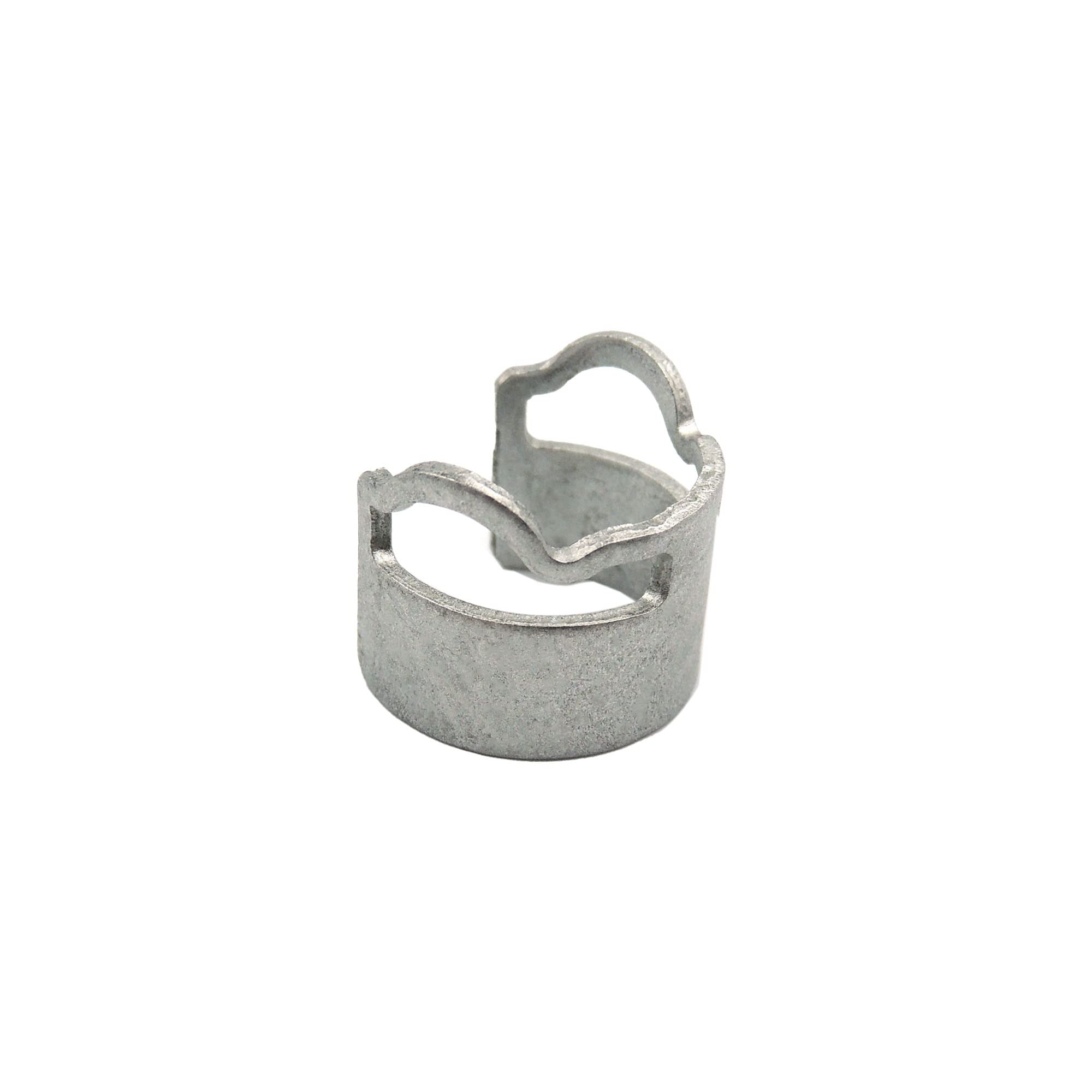
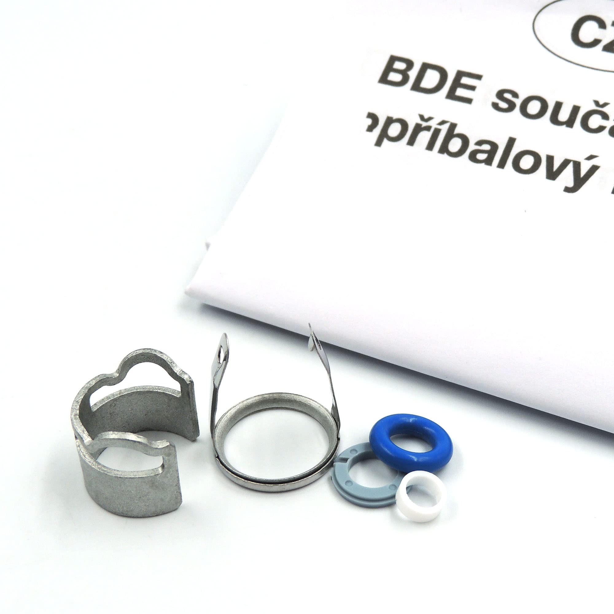
HiSport Fuel Injectors Seals Repair O-ring Kit - 06D998907 4-cylinder Replacement For Golf Jeta (1 pack)
Quantity:
Fraud Prevention: Your Payment is Safe & Secure.

- REPLACEMENT FOR : It Can Replacement For Golf 4Motion Jetta Fuel Injector Kit
- SUPERSEDED PART NUMBER:06D998907 06D 998 907 06F906036A 06F906036F 06F906036D 06F 906 036 A 06F 906 036 F 06F 906 036 D
- HIGH-QUALITY MATERIALS:Perfect Performanc.Easy Installation.High Reliability.We Use High-Quality Rubber o-Rings It Can Improve The Performance, And Easy To Install, High Reliability Our Products Are 100% Perfect Match For The Original Car. Our Products are 100% Perfect Match for the Original Car.
- SERVICE:Please confirm the product part number before purchase. If you are not sure whether it fits your car, please contact us
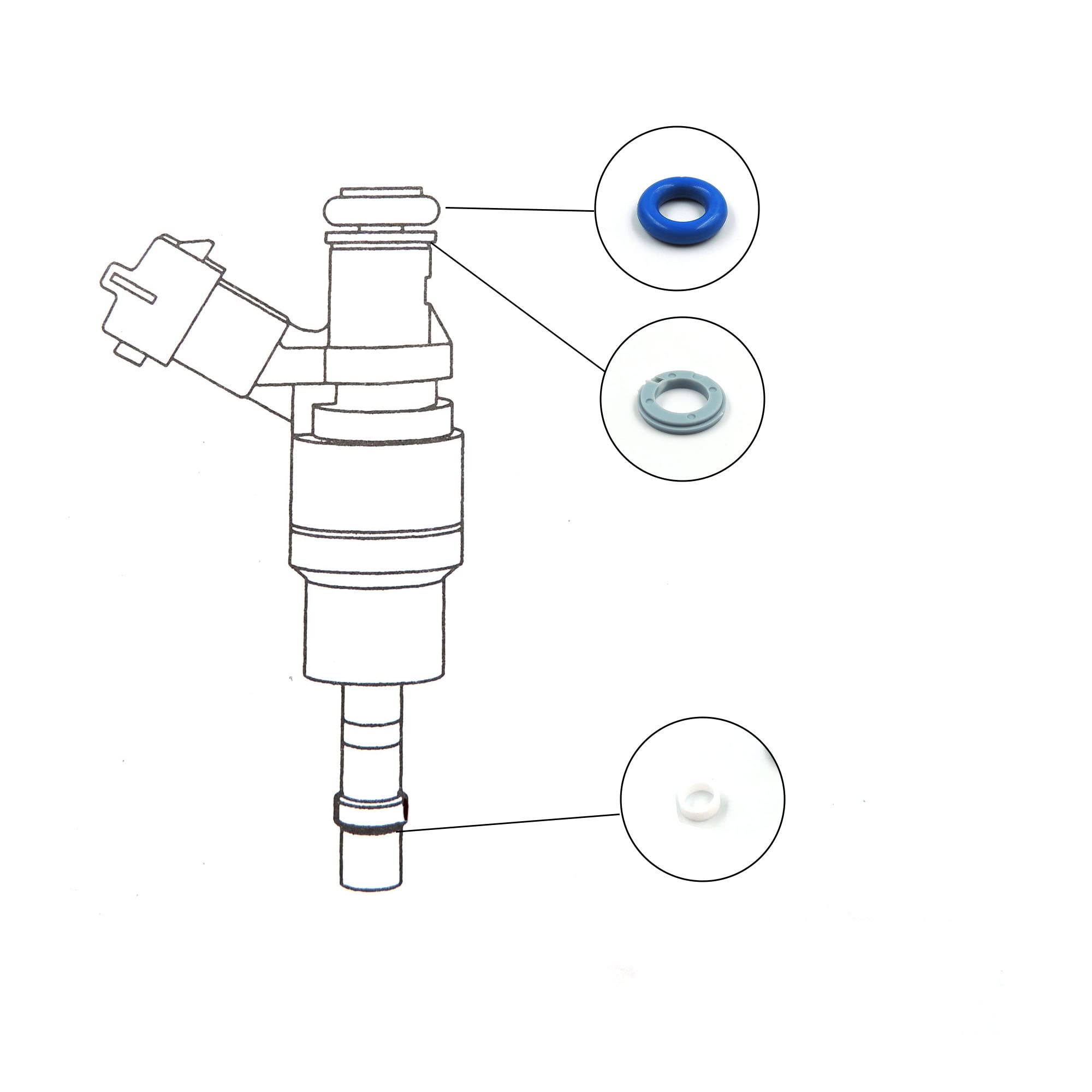
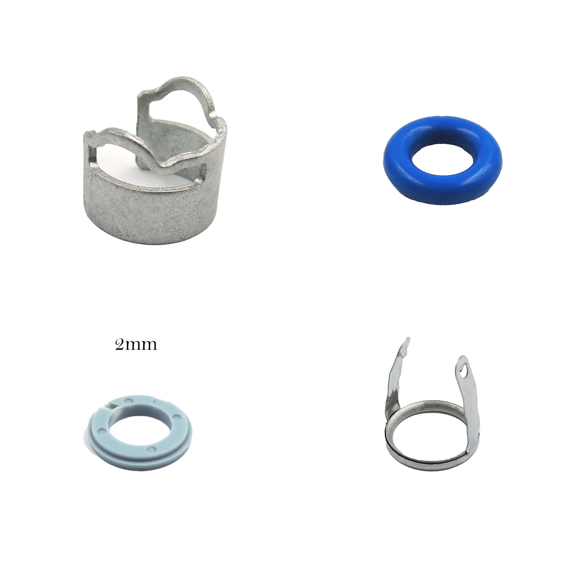
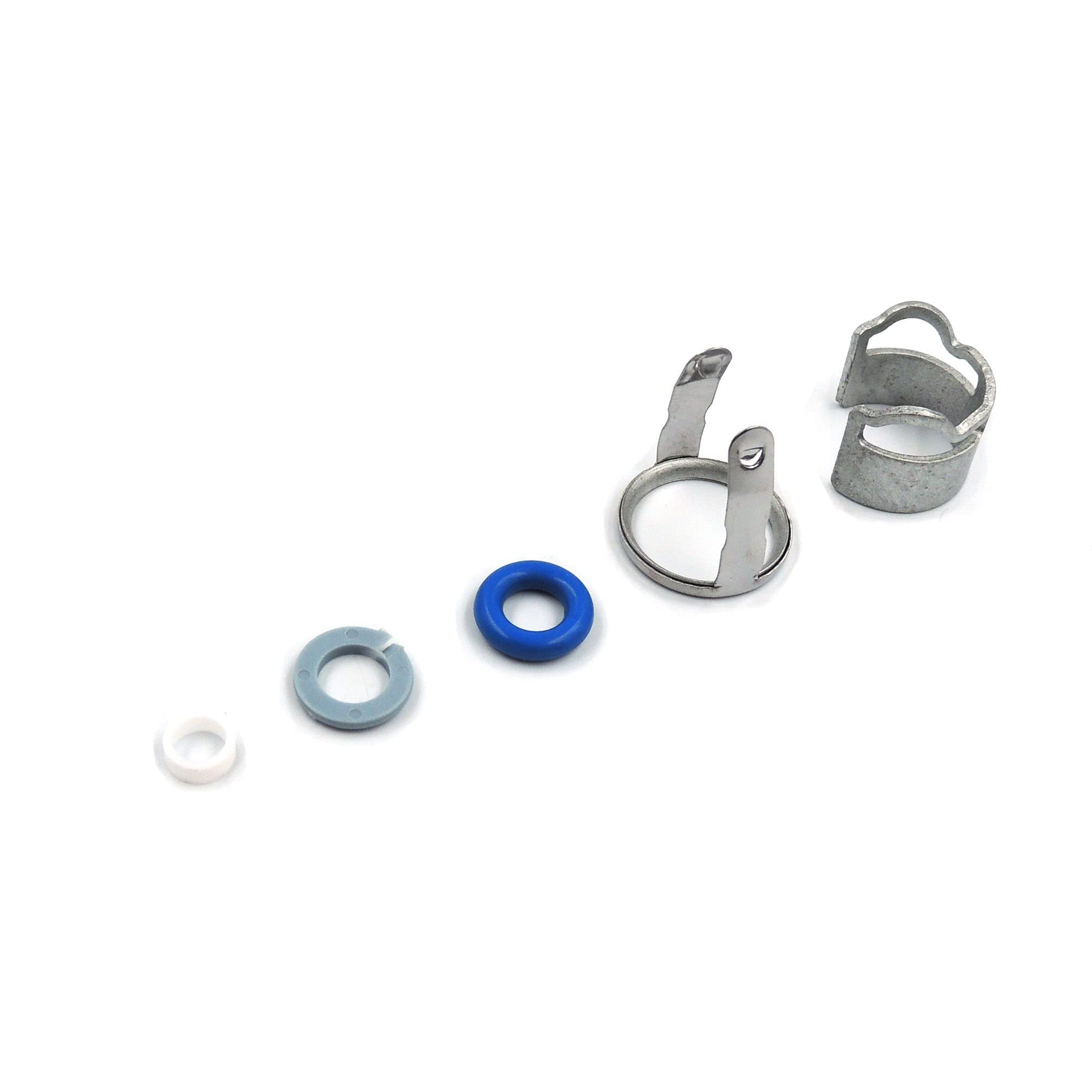
- WHAT YOU GET - 1Pack Fuel Injectors Seals Repair Kit

OE:06D998907
Perfect Performanc.Easy Installation.High Reliability.We Use High-Quality Rubber o-Rings It Can Improve The Performance
- Fit Model
- Bee--tle 2012---2016 2.0 TFSI CCTA/CBFA/CCZA
- Bee--tle Cabrio 2013---2016 2.0 TFSI CCTA/CBFA/CCZA

- Carefully clean cylinder head bore of high-pressure injection valve without using lubricant.Do not damage surface of bore.
Install high-pressure injection valve without lubricant in cylinder head (do not apply lubricant tocombustion chamber sealing ring).
- Figure 1: The O-ring (1) and combustion chamber sealing ring (3) must always be replaced.
- Figure 2:Removing combustion chamber sealing ring: Carefully remove old combustion
Chamber sealing ring (3) using a suitable tool. Do not damage groove or web in floorof groove.
- Figure 3: Position assembly arbour(A) on high-pressure injection valve(4).Pull new combustion chamber sealing ring (3) by hand over assembly arbour into groove of valve body.Do not use any lubricant. To calibrate the combustion chamber sealing ring, pushadjusting ring(B) with bevelled outer side all the way over the combustion chambersealing ring. Turn adjusting ring applying only moderate force 180° in one directionand then 180° back again to the starting position.

- Flgure 4: Do not increase diameter of support disk when installing.Turn like a screw over collar.Ensure support disk is installed correctly.
Flat side without step must face towards O-ring.
- Figure 5: Applying force to the plastic housing of the sensor will destroy component (A) To tighten, only apply force to the attached hexagon(B).
- Figure 6: Comply with tightening torque of plastic high-pressure sensor: 20...24 Nm
Note: The sensor has a taper seat. After tightening, an air gap(A) to the fuel distributorremains. Do not use additional seals and do not continue to tighten sensor.
